Test Bench
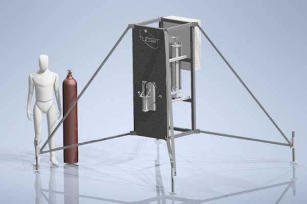
The test bench is designed as a stand-alone system to provide flexible testing capabilities and is equipped with a data acquisition and control system to allow for remote operation. In addition, the system is built as a compact setup for easy storage and transportation with standard vehicles. This allows for multiple test locations.

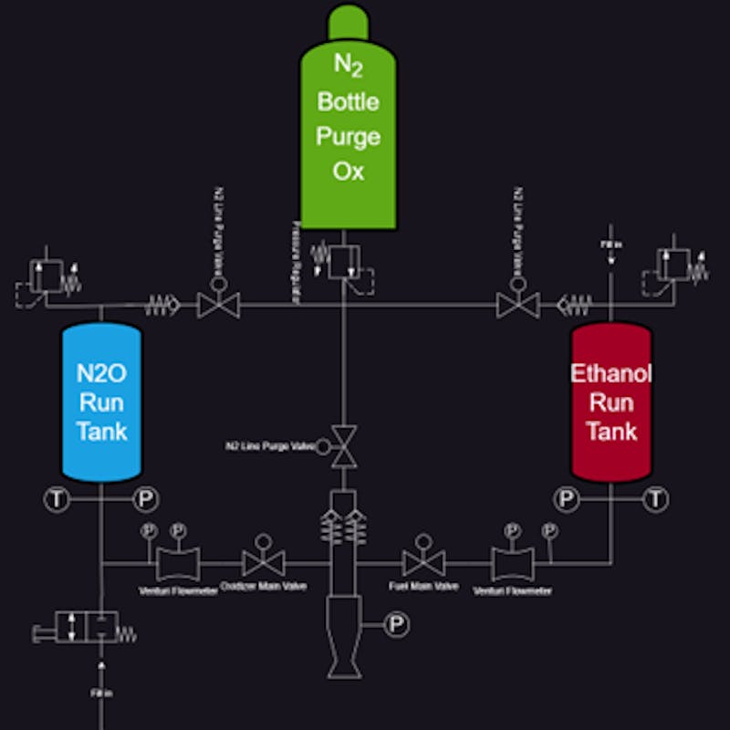
The main body of the test bench is supported by four legs to level the entire setup in the terrain. It contains the required piping, propellant tanks, etc. as shown in the P&ID below.
The main components of the piping are the nitrogen tank and the two propellant tanks. The propellant tanks have a similar architecture using an aluminum tube and two end caps that are bolted together. The tanks are designed for 200 bar according to Ad-2000 norm. A manual high pressure pump can be attached to the tanks and tested with water to test the pressure tanks. It is essential to test with an incompressible fluid due to the high risk involved when testing with combustible propellants. The tanks are equipped with safety valves to maintain a maximum pressure in the tank to prevent bursting. The operating pressure of the test bench is approximately 60 bar, depending on the propellant and the ambient temperature. Thus the safety valves have been chosen so that they open at 100 bar. Downstream of the tanks, mass flow meters, pressure and temperature sensors are installed to provide adequate test bench monitoring. The mass flow is controlled by the proportional main valves and supplies the engine with the required propellants. Nitrogen gas is used to pressurize the propellant tanks and provide sufficient purging of the system. This feature allows testing of injector designs using water, which requires fewer safety precautions.

The expected test bench specifications are listed below.


